- 您现在的位置:买卖IC网 > PDF目录262949 > MT48V8M16LFB4-75M:G 8M X 16 SYNCHRONOUS DRAM, 5.4 ns, PBGA54 PDF资料下载
参数资料
| 型号: | MT48V8M16LFB4-75M:G |
| 元件分类: | DRAM |
| 英文描述: | 8M X 16 SYNCHRONOUS DRAM, 5.4 ns, PBGA54 |
| 封装: | 8 X 8 MM, LEAD FREE, VFBGA-54 |
| 文件页数: | 46/80页 |
| 文件大小: | 2775K |
第1页第2页第3页第4页第5页第6页第7页第8页第9页第10页第11页第12页第13页第14页第15页第16页第17页第18页第19页第20页第21页第22页第23页第24页第25页第26页第27页第28页第29页第30页第31页第32页第33页第34页第35页第36页第37页第38页第39页第40页第41页第42页第43页第44页第45页当前第46页第47页第48页第49页第50页第51页第52页第53页第54页第55页第56页第57页第58页第59页第60页第61页第62页第63页第64页第65页第66页第67页第68页第69页第70页第71页第72页第73页第74页第75页第76页第77页第78页第79页第80页
PDF: 09005aef807f4885/Source: 09005aef8071a76b
Micron Technology, Inc., reserves the right to change products or specifications without notice.
128Mbx16x32Mobile_2.fm - Rev. M 1/09 EN
50
2001 Micron Technology, Inc. All rights reserved.
128Mb: x16, x32 Mobile SDRAM
Electrical Specifications
Notes:
1. MAX operating case temperature, TC, is measured in the center of the package on the top
2. Device functionality is not guaranteed if the device exceeds maximum TC during operation.
3. All temperature specifications must be satisfied.
4. The case temperature should be measured by gluing a thermocouple to the top center of
the component. This should be done with a 1mm bead of conductive epoxy, as defined by
the JEDEC EIA/JESD51 standards. Care should be taken to ensure the thermocouple bead is
touching the case.
5. Operating ambient temperature surrounding the package.
Notes:
1. For designs expected to last beyond the die revision listed, contact Micron Applications
Engineering to confirm thermal impedance values.
2. Thermal resistance data is sampled from multiple lots, and the values should be viewed as
typical.
3. These are estimates; actual results may vary.
4. Thermal impedance values were obtained using the 128Mb SDRAM 54-pin TSOP.
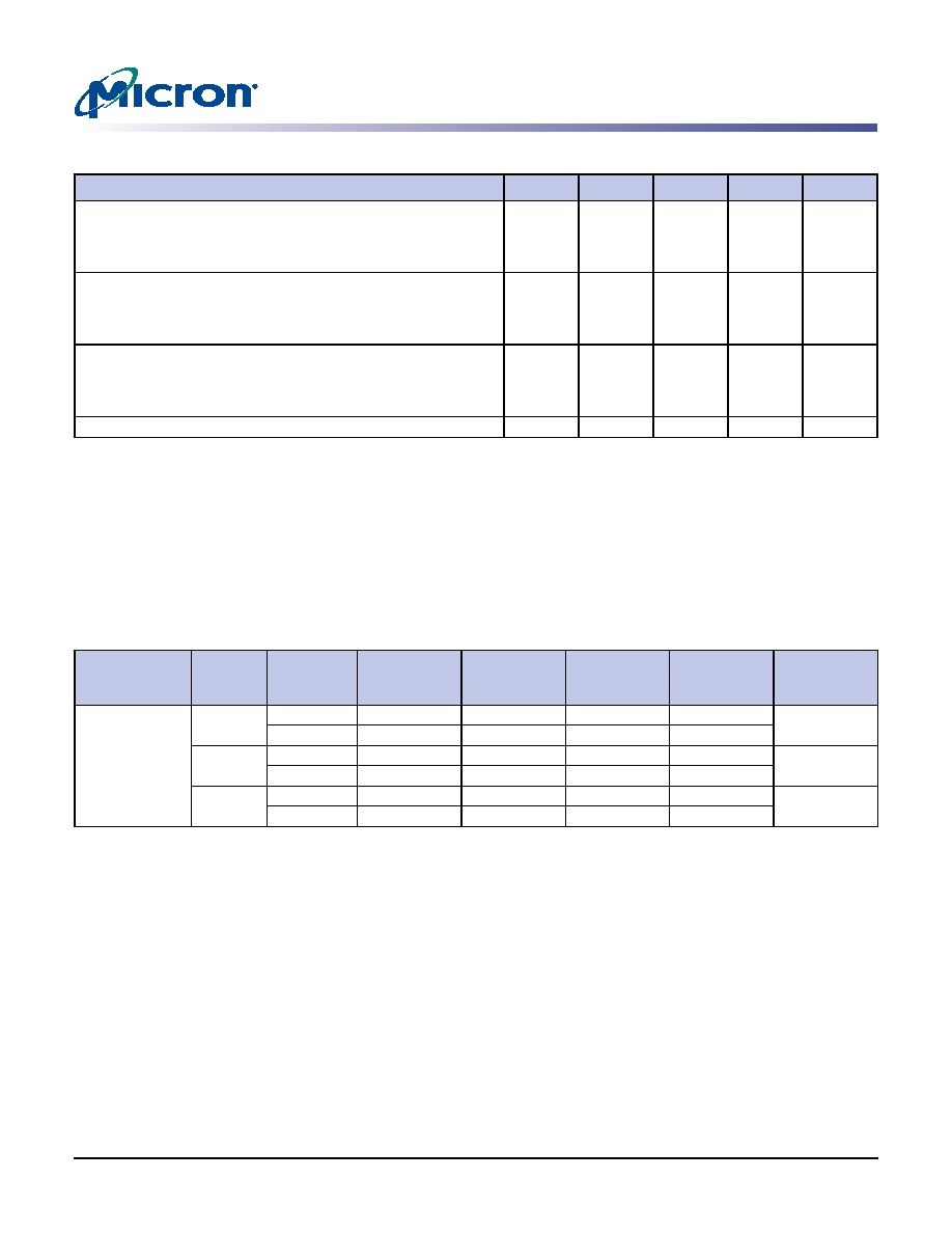
Table 13:
Temperature Limits
Parameter
Symbol
Min
Max
Units
Notes
Operating case temperature:
Commercial
Industrial
Automotive
TC
0
–40
80
90
105
°C
Junction temperature:
Commercial
Industrial
Automotive
TJ
0
–40
85
95
110
°C
Ambient temperature:
Commercial
Industrial
Automotive
TA
0
–40
70
85
105
°C
Peak reflow temperature
TPEAK
–260
°C
Table 14:
Thermal Impedance Simulated Values
Die Revision
Package
Substrate
θ JA (°C/W)
Airflow =
0m/s
θ JA (°C/W)
Airflow =
1m/s
θ JA (°C/W)
Airflow =
2m/s
θ JB (°C/W)
θ JC (°C/W)
G
54-pin
2-layer
86.2
67.8
62
46.9
11.3
4-layer
58.9
50.7
47.6
41.5
54-ball
VFBGA
2-layer
72.1
57.3
50.6
36.0
4.1
4-layer
54.5
46.6
42.8
35.5
90-ball
VFBGA
2-layer
64.6
50.8
45.3
37.5
1.8
4-layer
48.2
41.1
38.1
32.1
相关PDF资料 |
PDF描述 |
|---|---|
| MS8256FKXA-12 | 256K X 8 MULTI DEVICE SRAM MODULE, 120 ns, DMA32 |
| MT46V32M16BN-75IT | 32M X 16 DDR DRAM, 0.75 ns, PBGA60 |
| MT46V32M16P-6T | 32M X 16 DDR DRAM, 0.7 ns, PDSO66 |
| MT28F644W18FE-705KTET | 4M X 16 FLASH 1.8V PROM, 70 ns, PBGA56 |
| MPAT-122128-1003MS | 12200 MHz - 12750 MHz RF/MICROWAVE FIXED ATTENUATOR, 2.2 dB INSERTION LOSS-MAX |
相关代理商/技术参数 |
参数描述 |
|---|---|
| MT48V8M16LFB4-8 ITG | 制造商:Micron Technology Inc 功能描述:DRAM Chip Mobile SDRAM 128M-Bit 8Mx16 2.5V 54-Pin VFBGA Tray |
发布紧急采购,3分钟左右您将得到回复。